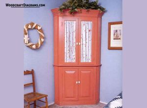
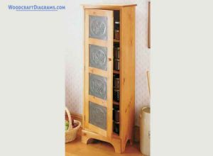
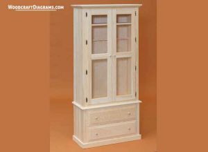
These corner wall cabinet plans and blueprints will help you construct a durable and beautiful cupboard.
The top and bottom both have storage shelves, so you can display lots of your favorite knickknacks with the doors open (or store lots of your un-favorite knickknacks with the doors closed). I used fabric in the top doors to match a bedspread, but you could substitute glass or solid panels like those in the lower doors if you like. The finished cabinet is approximately 40” wide, 78” high, and 20” deep.
The upper and lower sections of the cabinet are built separately and then joined together in the final assembly. Just take your time and follow each step carefully. This project takes a lot of work, but it’s well worth it. Countersink all nails and screws as you work so that the completed project is ready for finishing.
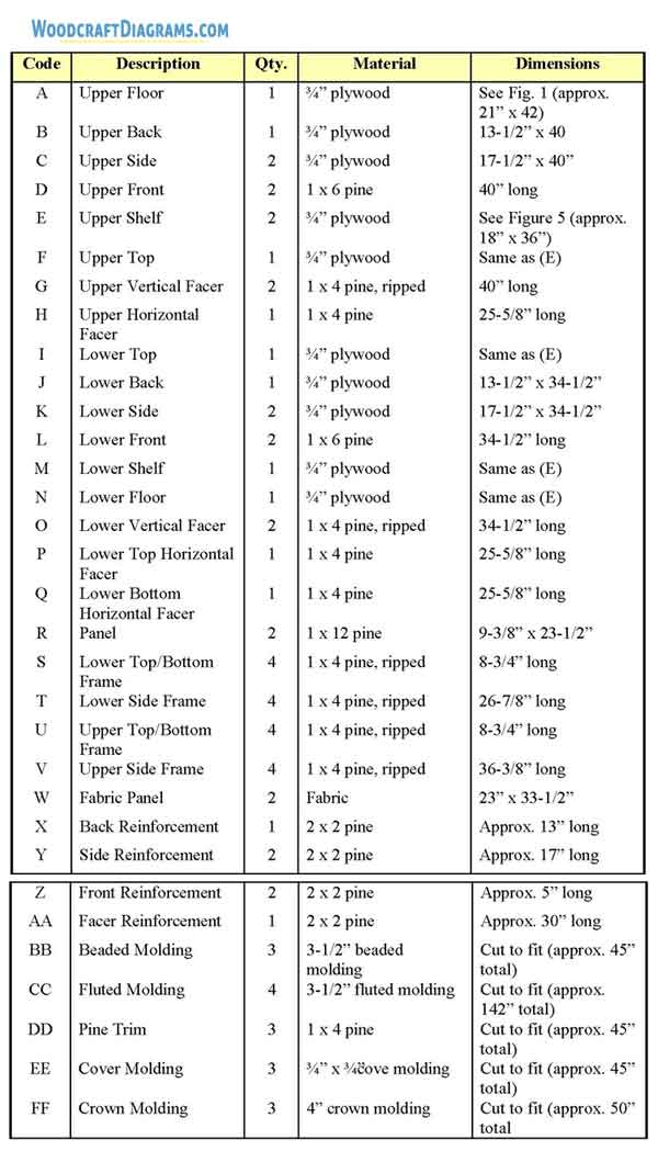
Using careful planning, this project can be completed using 2-1/2 sheets of plywood. To accomplish this, you must cut the narrowest pieces—the upper back (B), upper sides (C), and lower back (J)—from the half-sheet. Any other combinations require you to have three full sheets.
This cabinet requires extensive beveling and mitering, so I strongly recommend that beginners who want to tackle it enlist the help of an experienced woodworker. It’s not that the cuts themselves are difficult, but setting blade angles can be confusing until you know what you’re doing.
Constructing the Upper Section
Using Figure 1 as a guide, carefully measure and draw the outline for the upper floor (A) onto your ¾”-thick plywood; then cut out one upper floor (A).
Cut one 13-1/2” x 40” upper back (B) from ¾”-thick plywood.
Bevel both 40”-long edges of the upper back (B) at 22-1/2” degrees. Figure 2 shows the angle cuts for all of the beveled edges of the upper cabinet back and sides.
Cut two upper sides (C) from ¾”-thick plywood, each measuring 17-1/2” by 40”.
Bevel one of the 40”-long edges of each upper side (C) at 22-1/2 degrees and bevel the opposite edge at 45-degrees as shown in Figure 2.
Cut two upper fronts (D) from 1 x 6 pine, each 40” long.
Bevel one of the 40”-long edges of each of th4e upper fronts (D) at 22-1/2 degrees.
Bevel the opposite edge at 45 degrees.
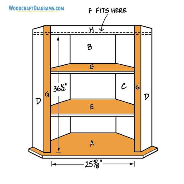
The assembly of the upper cabinet is shown in Figures 2 and 3.
You would probably be wise to enlist the assistance of a willing helper (or two) to accomplish this task.
Study both diagrams to familiarize yourself with how the pieces go together.
As shown in Figures 2 and 3, the upper back (B), upper sides (C) and upper fronts (D) stand on end on top of the upper floor (A).
The upper back (B) is set flush with the 13-1/2” edge of the upper floor (A), with its narrower face on the inside of the cabinet.
The upper sides (C) are flush with the 19-1/2” edges of the upper floor, and their 22-1/2-degree beveled edges fit against the matching beveled edges of the upper back (B).
Notice, however, that the 178-1/2”-long end of each upper side (C) is 2” shorter than the corresponding 19-1/2” edge of the upper floor (A).
The excess width of the upper floor (A) creates a small “shelf” between the upper and lower cabinet assemblies (see Figure 3).
This becomes an important design element in the finished project.
Begin by attaching the upper back (B) to the upper floor (A).
Glue the parts together and insert 1-1/4” screws through the bottom of the upper floor (A) and into the edge of the upper back (B), spacing the screws about 3” apart.
Fit the 22-1/2-degree beveled edge of one upper side (C) against the matching beveled edge of the upper back (B), positioning the side (C) so that its outer face is flush with the edge of the upper floor (A).
Glue the parts together and insert 1-1/4” screws through the upper floor (A) and into the edge of the upper side (C), spacing the screws about 3” apart.
Then insert 3d finishing nails through the bevel in the upper back (B) and into the beveled edge of the upper side (C), spacing the nails about 4” apart.
Repeat Step 9 to attach the remaining upper side (C) to the upper floor (A) and the upper back (B).
The next step is to add the two fronts (D), using Figure 2 as a guide. Note that he 45-degree beveled edge of each front (D) fits against the matching bevel on the adjacent upper side
(C). Glue the parts together and insert 1-1/4” screws through the upper floor (A) into the edges of the upper fronts (D), spacing the screws about 3’ apart. Secure the bevels with 3d finishing nails spaced about 4” apart.
Adding the Shelves and Top
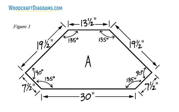
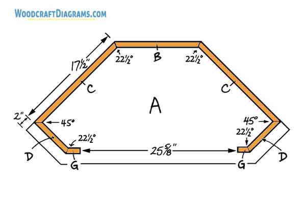
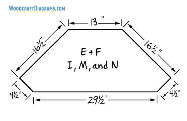
Figure 4 shows the dimensions of the two upper shelves (E) and the top (F). The shelves must fit exactly inside the assembly.
To assure a good fit, first cut a cardboard pattern of an upper shelf (E), using the dimensions provided in Figure 4.
Position the cardboard pattern inside your assembly, check the fit, and alter the pattern as necessary.
Then use the altered pattern to trace two upper shelves (E) and one upper top (F) onto ¾”-thick plywood, and cut out the plywood parts.
Place the assembly right side up on a level surface and decide where to place the shelves.
I positioned the first shelf 12” above that, but you may space the shelves as you like.
Next, measure and mark both the upper back (B) and upper sides (C) with the desired locations of the shelves.
The marks don’t have to be exact—your job will be much easier if you use a level to position the shelves rather than relying on measurements.
Fit the lowest upper shelf (E) inside the cabinet assembly as close as possible to your marks.
Place the level on the upper shelf (C) in several locations and facing in several directions, adjusting the position of the shelf until it is exactly level in every direction.
Use glue and 1-1/4” screws placed about 3” apart to attach the shelf in place.
Insert the screws through the upper sides (C), the upper back (B), and the upper fronts (D) into the upper shelf (E), countersinking each screw as you go.
Repeat Steps 3 and 4 to attach the second upper shelf (E) inside the upper cabinet assembly.
Fit the upper top (F) inside the upper cabinet assembly as you did when adding the shelves, positioning its lower face 3-1/2” from the top edges of the upper back, sides, and fronts (B,C, and D).
Use your level again to make sure that the top (F) is even in all directions.
Glue the upper top (F) in place and insert 1-1/4” screws, spaced about 3” apart, through the upper sides (C), the upper back (B), and both upper fronts (D) in to the upper top (F).
Installing the Facers
Cut two 40”-long upper vertical facers (G) from 1 x 4 pine.
Rip each of the upper vertical facers (G) to 2-1/4” in width.
Bevel one 40”-long edge of each upper vertical facer (G) at 22-1/2 degrees, as shown in Figure 2.
To avoid later problems with the doors, perform this next step without using any glue.
Using Figures 2 and 3 as guides, attach one upper vertical facer (G) to the left upper front (D), the two upper shelves (E), and the upper top (F).
Note that the 22-1/2-degree bevels on the upper vertical facer (G) and the upper front (D) face each other.
Secure the meeting beveled edges of the upper front (D) and the upper vertical facer (G) by driving two 3d finishing nails just far enough in to hold the piece in place.
Repeat Step 4 to attach the remaining upper vertical facer (G) to the right-hand side of the cabinet assembly, again omitting the glue.
Check the width of the opening between the two upper vertical facers (G) along the exposed edge of the top (F).
Also measure the width of the opening across the middle and bottom.
The opening should measure exactly 25-5/8”, or the doors will not fit properly. To adjust the opening, remove the two upper vertical facers (G) and alter them as necessary.
Then glue the adjusted facers in place and insert 1-1/4” screws through the upper floor (A) and into the bottom edges of the upper vertical facers (G).
Secure the meeting beveled edges of the upper front (D) and the upper vertical facer (G) with 3d finishing nails spaced about 6” apart.
Also drive nails through the facers (G) and into the edges of the shelves (E) and the upper top (F).
Cut one 25-5/8”-long upper horizontal facer (H) from 1 x 4 pine.
Fit the upper horizontal facer (H) between the two upper vertical facers (G) and position it so that its bottom edge is flush with the lower face of the upper top (F).
Drive two 3d finishing nails through the upper horizontal facer (H) into the edge of the upper top (F), hammering them in only far enough to hold the piece in place.
Now measure the opening from top to bottom on the left and right sides and in the middle.
It should measure exactly 36-1/2”, as shown in Figure 3. If necessary, remove the upper horizontal facer (H) and alter it so that the opening conforms to these measurements.
Replace the upper horizontal facer (H), glue it in place, and secure with 3d finishing nails placed about 3” apart and driven into the edge of the upper top (F).
Also toenail through the ends of the upper horizontal facer (H) into each of the upper vertical facers (G).
Constructing the Lower Section
The construction of the lower section is very similar to that of the upper section. There are several exceptions in the measurements of the parts and in the assembly process, however,
so follow the directions carefully.
The lower top (I) has exactly the same dimensions as the upper shelves (E). Use your cardboard pattern again to cut one lower top (I) from ¾”-thick plywood.
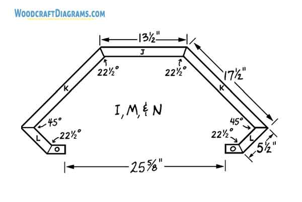
Cut one 13-1/2” x 34-1/2” lower back (J) from ¾”-thick plywood.
Bevel each of the 34-1/2”-long sides of the lower back (J) at 22-1/2 degrees, as shown in Figure 5.
Cut two lower sides (K) from ¾”-thick plywood, each measuring 17-1/2” x 34-1/2”.
Bevel one 34-1/2” edge of each lower side (K) at 22-1/2 degrees. Bevel the opposite edge at a 45-degree angle (see Figure 5)
Cut two 34-1/2”-long lower fronts (L) from 1 x 6 pine.
Bevel one of the 34-1/2”-long edges of each of the lower fronts (L) at a 45-degree angle. Bevel the opposite edge at 22-1/2 degrees.
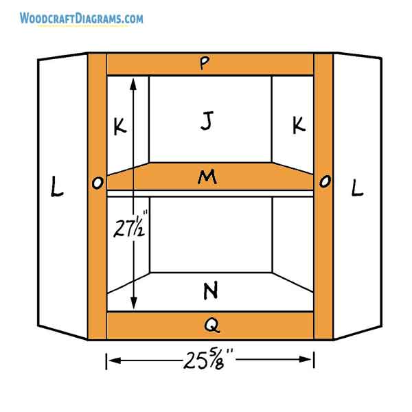
The assembly of the lower cabinet is shown in Figures 5 and 6. Again, enlist the services of a helper and study the diagrams before beginning the assembly.
For ease of handling, the lower cabinet is assembled upside down, with the lower top (I) serving as a base. Note that the lower back (J) and lower sides (K) fit onto the edges of the
lower top (I), not on its face. Make sure that the narrower faces of the beveled lower back (J) and the lower sides (K) are on the inside of the cabinet and that the 22-1/2-degree bevels are matched together.
Begin by gluing the lower back (J) to the lower top (I). Insert 1-1/4” screws, spaced about 3” apart through the lower back (J) and into the edge of the lower top (I).
Glue one lower side (K) to the lower top (I) and lower back (J), matching the 22-1/2-degree bevels. Insert 3d finishing nails, spaced about4” apart, through the lower back (J) and into
the beveled edge of the lower side (K). Insert 1-1/4” screws, spaced about 3” apart, through the lower side (K) and into the edge of the lower top (I).
Repeat Step 10 to attach the remaining lower side (K) to the lower top (I) and the lower back (J).
The next step is to add the two lower fronts (L), using Figures 5 and 6 as assembly guides.
Note that the 45-degree beveled edges of the lower fronts (L) and the lower sides (K) fit
together. Glue the lower fronts (L) in place and insert 3d finishing nails spaced about 3” through their beveled edges and into the beveled edges of the lower sides (K). Also insert
1-1/4” screws through the lower fronts (L) into the edge of the lower top (I).
Adding the Shelf and Floor
The lower shelf (M) and the lower floor (N) are the same dimensions as the lower top (I).
Use your cardboard pattern again to cut one lower shelf (M) and one lower floor (N) from ¾”-thick plywood.
Place the lower cabinet assembly upside down on a surface that is exactly level. Position
the lower shelf (M) inside it as you like. I positioned mine 13” from the lower top (I).
Measure and mark both the lower back (J) and the two lower sides (K) with the desired shelf location.
Fit the lower shelf (M) inside the lower cabinet assembly as close as possible to your marks. Use your level to make sure that the lower shelf (M) is exactly level in all directions.
Glue the shelf in place and insert 1-1/4” screws, spaced about 3” apart, through the lower sides (K), the lower back (J), and the lower fronts (L) into the edges of the lower shelf (M).
Fit the lower floor (N) inside the lower cabinet assembly as you did with the shelf (M), positioning what will be its upper face (when the cabinet is turned right side up) 3-1/2” from the exposed edges of the lower back, lower sides, and lower fronts (J, K, and L).
Again, level the lower floor (N) in all directions.
Glue the lower floor in place and insert 1-1/4” screws spaced about 3” apart through the lower fronts (L), the lower sides (K) and the lower back (J) into the lower floor (N).
Adding the Facers
Turn the lower cabinet assembly right side up. Cut two lower vertical facers (O) from 1 x 4 pine, each 34-1/2” long.
Rip each of the lower vertical facers (O) to 2-1/4” in width.
Bevel one 34-1/2”-long edge of each lower vertical facer (O) at 22-1/2 degrees.
Note in Figure 5 that the beveled edge of the lower vertical facer matches the beveled edge of the lower front (L). Attach one lower vertical facer (O) to the left lower front (L), the lower shelf (M), and the lower top (I), as shown in Figure 6, using two 3d finishing nails driven in just far enough to hold the pieces in place.
Repeat Step 4 to attach the remaining lower vertical facers (O) to the other side of the cabinet assembly.
Check the width of the opening between the two lower vertical facers (O) along the exposed edge of the lower floor (N), across the center of the opening, and across the top.
The opening should measure exactly 25-5/8”. If necessary, remove the two lower vertical facers (O) and alter them to make the opening conform to this measurement.
Then glue the two lower vertical facers (O) in place and drive 3d finishing nails, spaced about 4” apart, through the beveled edges of the lower fronts (L) into the edges of the lower vertical facers (O).
Also insert 1-1/4” screws through the facers (O). Also insert 1-1/4” screws through the facers (O) into the edges of the lower floor (N) and lower shelf (M).
From 1 x 4 pine, cut one 25-5/8” long lower top horizontal facer (P) and one 25-5/8”-long lower bottom horizontal facer (Q).
Fit the lower bottom horizontal facer (Q) between the two lower vertical facers (O), positioning it so that its top edge is flush with the upper surface of the lower floor (N). Glue the facer (Q) in place and secure it with 3d finishing nails driven through the facer (Q) and into the edge of the floor (N). Also toenail the ends of the facer (Q) to the edges of the lower vertical facers (O).
Fit the lower top horizontal facer (P) between the two lower vertical facers (O), so that it is flush at the top. Secure it temporarily by driving two 3d finishing nails through the facer (P) and into the edge of the lower top (I).
Hammer the nails in only far enough to hold the piece in place.
Now measure the opening from top to bottom on the left, middle, and right sides.
The opening should measure exactly 27-1/2”. If necessary, remove the lower top horizontal facer (P) and alter it so that the opening conforms to this measurement.
Glue the lower top horizontal facer (P) in place, securing it by driving 3d finishing nails through it and into the edge of the lower top (I). Space the nails about 3” apart.
Also toenail the facer by driving nails through its edge and into the lower vertical facers (O).
Constructing the Lower Doors
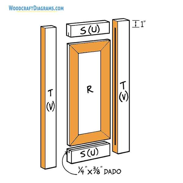
Each of the two lower doors (see Figure 7) consists of a center panel that is beveled on all four edges and inserted into a frame. This is not difficult to do, but it requires a certain amount of precision in cutting to obtain a professional-looking finished product.
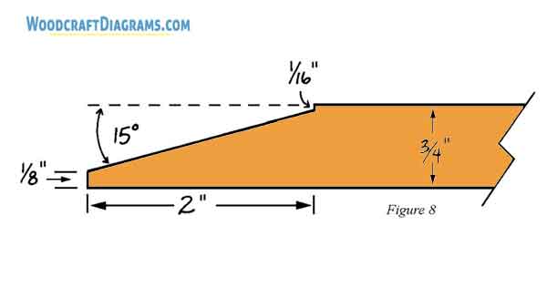
Start by cutting one 9-3/8” by 23-1/2” panel (R) from 1 x 12 pine.
Set your saw blade to cut at 15 degrees off vertical and bevel all four edges of the panel (R), leaving a thickness of 1/8” on the outside edges. A diagram of the resulting cut is shown in Figure 8.
Rip a total of 12 linear feet of 1 x 4 pine to 2” in width.
From the ripped 1 x 4 pine, cut two 8-3/4”-long lower top/bottom frame pieces (S) and two 26-7/8”-long lower side frame pieces (T).
Cut a dado ¼” wide and 3/8” deep down the center inside edge of each of the four frame pieces (S and T) to accommodate the center panel (R).
If you don’t want your dadoes to show (what would the neighbors think?) on the outer edges of the doors, then start the dado 1” from one end of each lower side frame piece (T) and stop it 1” from the other end.
Place the panel (R) into the dadoes cut in the frame pieces to make sure that all of the pieces fit together properly.
An optional step at this point is to rout a decorative design into the inside edges of the frame pieces.
Because this is difficult to do with the panel installed, simply clamp the frame together securely and rout the inside edges. Then place the panel (R) inside the frame.
As shown in Figure 7, the top and bottom frame pieces (S) fit between the side frame pieces (T). Glue and clamp the frame pieces together, with the panel (R) in place but not glued into the dadoes.
Fasten the frame together by inserting 8d finishing nails at all four corners.
Repeat to assemble the second lower door.
Constructing the Upper Door Frames
The upper doors are constructed in the same manner as the lower doors, but they don’t have raised panels in their centers.
Instead, the upper doors are completed by adding fabric after the cabinet has been stained or painted. Start by ripping a total of 16 linear feet of 1 x 4 to 2″”in width.
From the ripped pine, cut two 8-3/4”-long upper top/bottom frame pieces, (U) and two 36-3/8”-long upper side frame pieces (V).
Glue and clamp the four frame pieces (U and V) together as shown in Figure 7, making sure to fit the upper top/bottom frame pieces (U) between the upper side frame pieces (V).
Then drive 8d finishing nails into all four corners of the frame.
If you routed a decorative design onto the lower doors, you may want to rout one into the inside edges of the assembled frame at this stage.
Repeat Steps 1 through 3 to make the second upper door frame.
Hanging the Doors
Set the cabinet assemblies on their backs so that you don’t have to support the weight of the doors while you hang them.
Set both of the upper doors inside the opening in the upper cabinet assembly.
If you’re using exposed hinges, position them equidistant from the top and bottom on the outside of each door and secure them in place using the screws provided by the manufacturer.
For other kinds of hinges, follow the manufacturer’s instructions for installation.
Repeat Step 2 to attach the two lower doors to the lower cabinet assembly.
Attach the four cabinet handles (one on each door), following the manufacturer’s directions.
Completing the Base
The lower back (J), lower sides (K), lower fronts (L), and lower vertical and horizontal facers (O, P, and Q) form a 3-1/2”-wide collar at the bottom of the lower cabinet.
In orderto support the weight of the cabinet, this collar must be strengthened with 2 x 2 pine reinforcements.
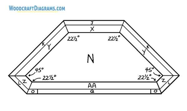
As you can see in Figure 9, the reinforcements must be mitered to fit the beveled edges of the pieces they reinforce.
The lengths specified above give you some excess for mitering room. Measure and miter carefully so that all of the reinforcements fit properly.
Start by mitering both ends of the back reinforcement (X) at 22-1/2 degrees.
Then miter each of the side reinforcements (Y) and front reinforcements (Z) to create a 22-1/2-degree cut atone end and a 45-degree cut at the other end.
Finally, miter both ends of the facer reinforcement (AA) at 22-1/2 degrees.
Fit the back reinforcement (X) against the lower back (J) and under and against the lower floor (N). Glue it in place and insert 2” screws, placed about 3” apart, through the back reinforcement and into the floor (N) and lower back (J).
Fit the two side reinforcements (Y) in place, matching the miters as you do. Glue them to the lower sides (K) and lower floor (N) and insert screws as in Step 5.
Fit the two front reinforcements (Z) in place, again matching the miters. Glue them to the lower fronts (L) and lower floor (N) and insert screws as in Step 5.
Fit the facer reinforcement (AA) in place. Glue it to both vertical facers (O), the lower bottom horizontal facer (Q), and the lower floor (N). Then insert screws as in Step 5.
Assembling the Cabinet
Place the upper cabinet assembly on top of the lower cabinet assembly, matching the upper and lower assemblies at the back and on the sides.
If you want to be able to separate the two assemblies (during a household move, for example), use only screws –not glue—so that you can unscrew the two halves for easier moving.
Insert 1-1/4” screws through the lower top (I) into the upper floor (A).
You can reverse the direction of the screws, but the heads will be visible unless you countersink and fill them, making this a permanent attachment.
Use two or three screws across the back, two or three in the middle, and three or four across the front.
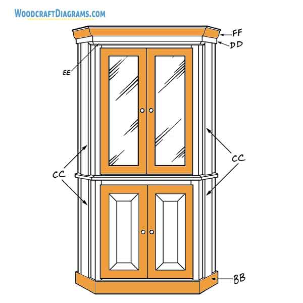
Adding the Trim
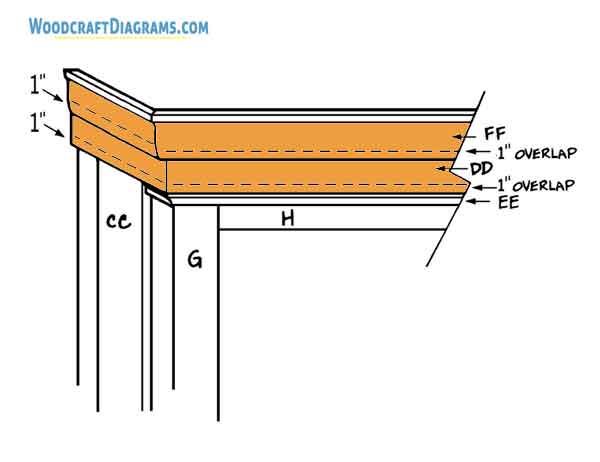
Study Figure 10, which shows the pine trim (DD), cove molding (EE), and crown molding (FF) added to the cabinet top; the fluted trim (CC) added to both sides; and beaded molding (BB) added to the bottom.
Because the back and sides of the cabinet fit against the wall, no molding is added to them.
Carefully measure and cut two 6-1/2”-long pieces of beaded molding (BB) to fit across the lower fronts (L) at t he bottom of the cabinet and one 32”-long piece to fit across the lower facers (O and Q).
Miter one end of each shorter piece and both ends of the long piece at 22-1/2 degrees.
Glue the mitered pieces of beaded molding (BB) to the cabinet and secure with 3d finishing nails space about 3” apart.
Measure and cut two pieces of fluted molding (CC) to fit down the center of each of the lower fronts (L), between the upper floor (A) and the beaded molding (BB) that you just installed.
Each piece should be approximately 31” long. Glue the pieces in place and secure with 2d finishing nails spaced about 4” apart.
Don’t glue the end of the fluted molding (CC) to the upper floor (A) if you plan to separate the upper and lower assemblies at some future time.
Measure the length of each upper front (D) along its center, starting at the upper floor (A) and extending 2-1/2” higher than the top of the opening for the upper doors.
This length should be approximately 39”. Cut two pieces of fluted molding (CC) to this length.
Glue the pieces in place and secure with 2d finishing nails spaced about 4” apart.
Following the same procedures described in Step 2, measure, cut, and miter 1 x 4 pine trim (DD) to fit around the top of the cabinet.
The lower edges of the shorter trim pieces (DD) fit on top of the fluted molding (CC) that you attached in Step 4.
Note that the pine trim (DD) will extend above the upper surface of the cabinet.
Glue the trim in place and secure with 1-1/4” countersunk screws.
Again following the same procedures, measure, cut, and miter ¾” x ¾” cove molding (EE) to fit across the top of the cabinet.
Use glue and 3d finishing nails to attach the cove molding just below the 1 x 4 pine trim (DD) that you added in Step 5.
The ends of the cove molding (EE) stop at the edges of the fluted molding (CC).
The final addition is the crown molding (FF) that fits across the very top of the cabinet.
Following the procedures in Step 5, attach the crown molding (FF) so that it overlaps the top of the 1 x 4 pine trim (DD) by 1”.
Finishing the Wood
Fill all nail and screw holes with wood filler.
If you want to be able to disassemble the cabinet for transport, don’t cover the screw holes in the lower top (I), as these screws hold the two assemblies together.
Sand all the surfaces thoroughly.
Check the fit of each pair of doors. If they bind or scrape the edges of the opening, sand or plane them as necessary.
Stain or paint the cabinet and all four doors the color of your choice.
Adding the Fabric
Cut two 23” x 33-1/2” fabric panels (W) for the upper doors.
Sew gathering stitches ¼” from the edge along both 23”-long edges of one fabric panel.
Pull the gathering stitches until the panel measures 11-3/4” across the top and bottom.
Hot-glue or tack the gathered panel to the inside of one upper cabinet door. Trim the gathered edges with scissors, then glue upholstery braid around all four edges of the gathered panel to conceal the gathering stitches.
Repeat Steps 2 through 4 to stitch and attach a fabric panel to the inside of the remaining upper door.
Now sit down, lean back, and admire your work!